By Stu Asay, PE, PhD
Testers arriving at a service connection that cannot be out of service recognize the importance of two similar backflow preventers installed in a parallel configuration. In fact, some manufacturers produce a wye fitting for the inlet and outlet, so matched backflow preventers can be installed. Note the use of the term ‘matched.’ Let’s address that for a moment.
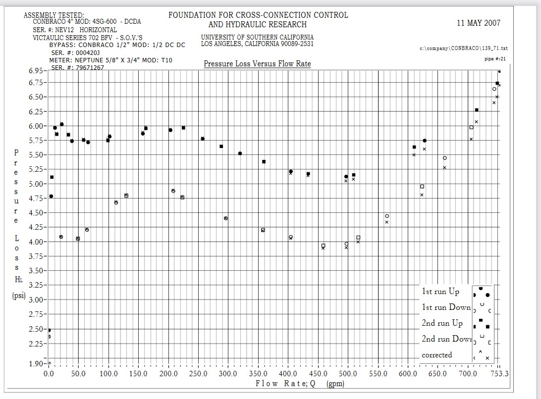
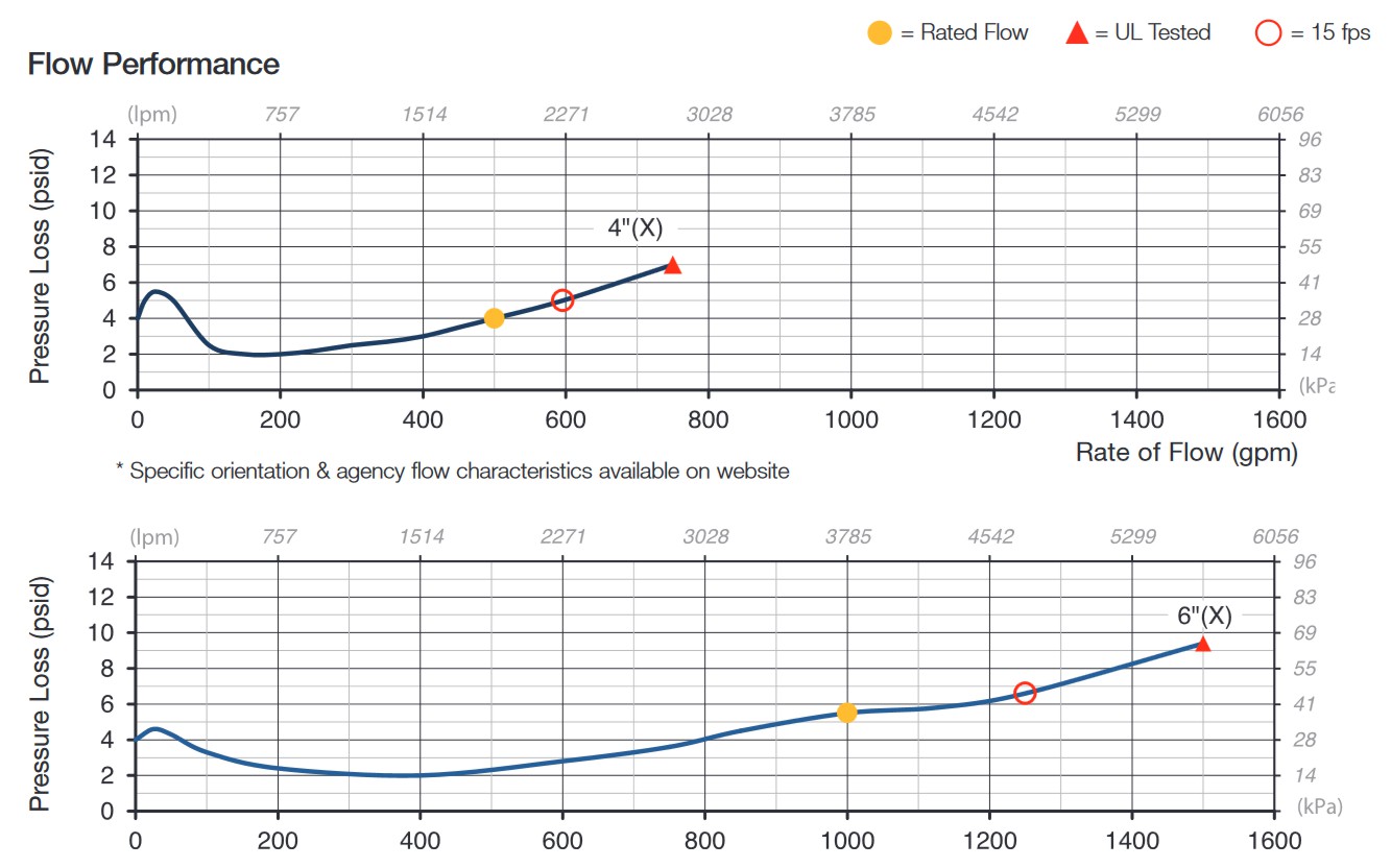
If you’ve compared a manufacturer’s flow/loss curve between two models or even two manufacturers, you observed the curves are not an identical match. For example, note the no flow static loss. Do they all start at 3.8 psi? With flow, water works to open the check valves and the loss curve tapers off slightly. Does that ‘bump’ occur at the same flowrate?


Occasionally, a tester may service one of the parallel assemblies due to corrosion from its coating loss or elastomer component softening. A preventative maintenance measure might lead to opening the second assembly for comparison. If one needs service, certainly the second will need work.
The technician opens the second assembly and discovers that internally there’s very little if any wear. Indeed, in many respects it looks like a new assembly. How can that be? Let’s assume that the flow loss curves were not evenly matched. The second assembly had a slightly higher loss (flow resistance) than the first. Water opened the checks on the first assembly allowing flow before the second assembly checks opened? Have you ever noticed how rare it is to find identical check valve values? Okay, capture that thought for a moment as we move to a similar type of assembly.
A double check (or reduced pressure principle) detector assembly is a unit consisting of two assemblies in parallel. The larger or mainline assembly provides flow to a fire-suppression system, while the smaller bypass allows flow through a flow indicator or meter that detects system leakage or unauthorized water usage. In this case, the two parallel assemblies do not have evenly matched flow loss curves. The main line has a slightly greater resistance to flow allowing the lower flows through the detector. To make this discussion complete, we might include the Type II detector assembly, where the bypass meter and check detects flow around the second check only.
One troubleshooting point that is regularly taught in quality tester training programs is that check valve elastomers can soften with time, when exposed to water. For example, a newly installed assembly has a first check differential of 2.4 psid. A year later, the same check has a reading of 2.1 psid. Two years from the installation date the check holds tight at 1.6 psid. This remains a passing value greater than 1 psid. In this theoretical example, if one check’s closing differential drops 0.8 psid and the second check deteriorates at the same rate, the overall differential loss would be 1.6 psid for the assembly.
How might a loss like this – or greater impact the performance of the detector assembly and its ability to bypass low flows? Consider the individual performing the field test on a detector assembly. The unit will ‘pass’ if each check has a minimum differential of 1.0 psid. But does the assembly perform as it did when it was new, if there was an assembly differential reduction of 2.0 psid? The tester was not trained to know or determine that bypass ‘breakthrough’ threshold. Should testers be trained to add the differential readings of the mainline check valves and compare them to the manufacturer’s loss curve? If that value is 2 psid lower than the zero flow loss on the curve, might that be a failure and reason for new elastomers? Or what if the manufacturers provided a minimum combined check one and two loss for the bypass to function? When considering the Type II assemblies, this approach might be easier to compare the loss with a single check valve. Then there might be another tester option of simply opening the number 4 test cock on the mainline assembly to a flow less than 2 gpm, for example. The meter on the bypass should register that flow.
Finally, the American Society of Sanitary Engineering’s Series 5000 standard contain field test protocols for detector assemblies. In addition to performing an assembly test on the mainline and bypass units, the tester is advised to verify that flow will simply pass through the bypass connections to the mainline assembly. Is simply opening a test cock on the bypass assembly an indication that the ¾ inch tap is free of any corrosion obstruction? If corrosion is in fact obstructing 60-70 percent of the opening, would that have any effect on the detector’s flow characteristics?
As always, the Backflow Prevention Institute is interested in your thoughts and feedback on this conversation. We look forward to your return flow.


 09 Nov 2020
 Posted by Stu Asay


