The question is often asked, are backflow prevention assemblies necessary on fire sprinkler systems? Other questions include, do they need to be installed on residential fire protection systems if that system is part of the domestic water system suppling plumbing fixtures and appliances? Is the backflow protection installed on fire protection systems to protect the potable water system worth the pressure and volume loss that results from the installation of cross-connection protection? Have there ever been a documented case of individuals becoming ill or dying because of a backflow incident with a water based fire protection system? Has a documented cross-connection problem occurred with a fire protection system in the last year, or for that matter the last five years? These are questions frequently heard in cross-connection control discussions and in public meetings where the rules and regulations concerning the installation and testing of backflow prevention are debated and legislation is created, repealed, or amended.
Those of us in the industry know that cross-connection programs in many areas have vastly reduced the number of reported incidents that occur within our water systems. This has at times resulted in people believing that backflow issues and problems no longer exist or that there may never really have been an issue in the first place. This thinking can be both counterproductive and dangerous. Backflow occurrences in water systems are a result of changes in pressure within that system. That is simply a fact. There is no water system in existence that does not or will not have pressure fluctuations. Sooner or later every water system loses its pressure completely. The question is not if but when it will happen. This is why we need to look at what protection is needed, educate the consumer and the public of the possible hazards and then provide the necessary devices or assemblies to match the hazard which exists. Every system may not need a reduced pressure principle backflow assembly. In far too many areas we have an all or nothing approach to backflow protection. We need to look at each installation for the hazard it presents and then install the proper protection.
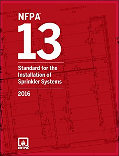 When deciding on the proper system protection there are several considerations we need to look at. In my mind there is no one size fits all situations in the cross-connection world. Each and every installation should be looked at on an individual basis as a unique stand-alone system. The National Fire Protection Association NFPA 13 Standard for the installation of sprinkler systems contains the requirement for the sprinkler systems themselves. Fire protection system are designed to match the hazard that exists in the locations they are installed in. As building types and contents of these buildings can be very different, we need to understand that the fire protection system for any installation needs to be designed and installed to meet that specific hazard or need. An aircraft hangar will need a very different fire protection system than the system required in an apartment building. The backflow protection requirements for these two examples would also differ greatly.
The adopted plumbing code addresses the protection needed on the potable water supply line that supplies the fire protection system in most installations. It also takes into consideration the issues that may present themselves as a result of the addition of private fire hydrants or fire department connections within fire protection systems. Looking at the 2018 Uniform Plumbing Code several factors can come into play regarding the installation of backflow protection. UPC Chapter 6 Section 603.5.14 Protection from Fire Systems states:
Except as provided under Section 603.5.14.1 and Section 603.5.14.2, potable water supplies to fire protection systems that are normally under pressure, including but not limited to standpipes and automatic sprinkler systems, except in one – or two – family or townhouse residential sprinkler systems, piped in materials approved for potable water distribution systems shall be protected from backpressure and backsiphonage by one of the following testable devices:
(1) Double check valve backflow prevention assembly (DC)
(2) Double check detector fire protection backflow prevention assembly
(3) Reduced pressure principle backflow prevention assembly (RP)
(4) Reduced pressure detector fire protection backflow prevention assembly
Potable water supplies to fire protection systems that are not normally under pressure shall be protected from backflow and shall be in accordance with the requirements of the appropriate standards referenced in Table 1701.1.
 The adopted plumbing code does make a difference between residential and commercial systems however this is limited to systems which use potable water piping materials only. A stand-alone system using non-potable piping materials will require the same level of protection as a commercial system. The code also goes further and in Section 603.5.14.2 Chemicals, the code discusses the addition of chemicals to a system and increases the required level of protection in these cases. The code states:
Where antifreeze, corrosion inhibitors, or other chemicals are added to a fire protection system supplied from a potable water supply, the potable water system shall be protected by one of the following:
(1) Reduced pressure principle backflow prevention assembly (RP)
(2) Reduced pressure detector fire protection backflow prevention assembly
It is important to realize that a reduced pressure principle assembly has a much higher pressure and volume loss than does a double check valve assembly. The relief valve on a reduced pressure principle assembly also can present installation and future drainage issues that must be consider when designing and installing new systems, or when retrofitting protection on existing systems. The protection installed should match the degree of hazard to the potable water supply. Installing high hazard protection at a greater cost and pressure loss, when low hazard protection is need does a disservice to the customer and end user.

Reduced Pressure Detector Assembly (ASSE 1047)
Another issue the plumbing code addresses is the addition of a fire department connection. Section 603.5.14.1 Fire Department Connection states:
Where fire protection systems supplied from a potable water system include a fire department
(Siamese) connection that is located less than 1700 feet (518.2 m) from a non-potable water source that is capable of being used by the fire department as a secondary water supply, the potable water supply shall be protected by one of the following:
(1) Reduced pressure principle backflow prevention assembly (RP)
(2) Reduced pressure detector fire protection backflow prevention assembly
Non-potable water sources include fire department vehicles carrying water of questionable quality or water that is treated with antifreeze, corrosion inhibitors, or extinguishing agents.
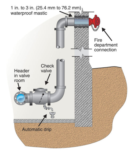
A Fire Department Connection (Figure A-8.16.2 from the Backflow Prevention Manual)
Fire department connections can be an issue when used in fighting a fire. Firemen by and large are not concerned with backflow prevention issues. They are concerning with protecting people’s lives and to a lesser extent their property. Getting the necessary volume of water on a fire is their mission and they will use water from any source available to achieve that goal. This can create cross-connection control problems and may as a result mean that the level of protection on the fire protection system may need to be increased to a high hazard protection level.
The code also looks at the design of the systems themselves Section 603.5.14.3 Hydraulic Design states: Where a backflow device is installed in the potable water supply to a fire protection system, the hydraulic design of the system shall account for the pressure drop
through the backflow device. Where such devices are retrofitted for an existing fire protection system, the hydraulics of the sprinkler system design shall be checked to verify that there will be sufficient water pressure available for satisfactory operation of the fire sprinklers.
Standpipe systems are used in many facilities, these systems are designed to provide water to fire hose connections or hose cabinets strategically installed inside a building. These systems usually are installed in large, open spaces within buildings, and in multistory buildings for the purpose of manual firefighting. Standpipe systems can provide early fire suppression in these buildings making it capable for a single individual or firefighter to offer a quick and effective response to fire. There are two types of standpipe systems, the first type, are dry systems, which normally contain no permanent water supply and are pressurized through a fire department connection by fire personnel responding to an incident. A dry standpipe system requires no backflow prevention protection. The second type is a wet standpipe system which is normally connected to the buildings potable water system and requires the installation of a double check valve assembly.
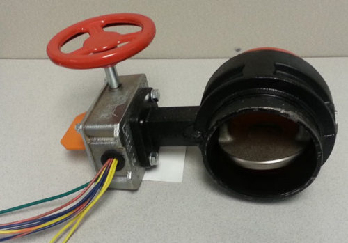
Backflow preventers on fire systems also must have indicating shutoff valves and these valves must be supervised. All control valves must have components that visually indicate whether the valve is open or closed. This list includes some of the most common types of valves, such as:
- Outside screw and yoke valves (OS&Y)
- Butterfly valves
- Post indicator valves (PIV)
- Wall indicator valves (WIV)
- Ball valves
For a fire-sprinkler system to operate, the control valve or valves must remain open and the system must be continuously monitored. Therefore, there is a device on each control valve that either prevents the valve from being closed or sends an alarm when it is closed. This device can be as simple as a locked chain through the control valve that prevents that valve from opening, or an alarm system that notifies the fire department when the valve is closed. Some systems utilize both methods. NFPA 13 refers to all such devices as supervisory devices.

As we have stated before backflow prevention devices and assemblies reduce pressure and volume available to the life safety and property protection systems. Careful selection of the proper and necessary protection for the potable water supply is important, but one size fits all approaches are never correct. Each system type needs to be looked at to be evaluated correctly. If we are looking at water based systems, there are four basis types that we encounter. Although they may be similar in some aspects they are also very different. Automatic fire-sprinkler systems consist of an arrangement of piping installed throughout the building that is designed to supply a sufficient amount of water under pressure to an open sprinkler head. Most fire sprinkler heads, except sprinkler heads on a deluge system are kept closed by a heat-sensitive operating mechanism. Typically, this operating mechanism is either a fusible link or a glass bulb. Regardless of the operating mechanism, only the sprinklers that are exposed to heat will open during a fire.
Wet pipe systems are installed in areas where the ambient temperature is maintained at or above 40°F. When a sprinkler is activated by heat from a fire, water flows immediately from the sprinkler head. These systems have water in the pipe at all times. In situations where there is a need to provide sprinklers in an unheated area, such as a small loading dock, an antifreeze system can be used. The addition of this chemical additive will require the installation of a high hazard protection assembly.
Dry pipe systems usually are installed in large, unheated areas, such as parking garages. These systems have pressurized air or nitrogen in the pipe, which keeps the main dry-pipe valve closed. When a sprinkler activates due to heat, the air is released, allowing the dry-pipe valve to open, filling the system with water, which is discharged through the open sprinkler head to suppress the fire.
Pre-action sprinkler systems usually are installed in areas where water could cause catastrophic damage, such as in freezers, computer rooms, and areas with electronic equipment. The piping in a pre-action system contains air or nitrogen, which can be pressurized or non-pressurized. Water to the system is held back by the pre-action valve, which is connected to a fire detection system. If a fire occurs, the detection system sends a signal that opens the pre-action valve, which then allows water into the system’s piping. The water is discharged through the open sprinkler.
Deluge systems are designed so that all the sprinkler heads are open and the piping is not pressurized. These systems usually are installed in areas where the possibility of a severe fire condition is likely, such as aircraft hangars. Water to the system is held back by the deluge valve, which is connected to a fire detection system. If a fire occurs, the detection system sends a signal that opens the deluge valve, which then allows water to discharge from all of the sprinklers on the system.
 Personnel working on each of these systems require special skills and knowledge to ensure the systems are tested and maintained properly. Certified Backflow testers must have an understanding of the system types and the requirements for flow testing and other items when these systems are returned to service. The NFPA 25 Standard covers the maintenance and testing of sprinkler systems and a thorough knowledge of these requirements are vital to anyone working on or testing backflow prevention assemblies within these systems. Backflow protection is needed on all types for sprinkler systems. While it may be more essential on larger more complicated systems, it is still indispensable protection on even the most basis installations. We need to again understand that every installation is in some way unique and that backflow prevention is needed. The laws of physics remain the same, residential or commercial, large or small, protecting the potable supply must be our common goal.
About the Author |
|
 |
Sean is a 40 year member of the United Association Local 524 Scranton Pa. He has worked in all phases of the plumbing and mechanical industry and is a licensed master plumber. Sean is a Past President of the American Society of Sanitary Engineering. Sean is also the member of the ASSE Cross-Connection Control, Technical Committee. Sean is employed by IAPMO as the Vice President of Operations for the IAPMO Backflow Prevention Institute. |


 05 Jun 2018
 Posted by Sean Cleary


