Question: I need to repair a 2” Febco model 825Y. Can you give me some history on this assembly? Will I need any special tools for disassembly?
Mark:
Febco began producing the model 825Y in 1978 and is still in production today. It is a reduced pressure principle assembly and is offered in ¼ – 2” sizes. This series uses poppet style check valves. Early models of the 825Y series did not have replaceable check seats. In 1994 replaceable check seats became standard. The only special tool required is used when replacing the check seats. A lead free version (LF825Y) was introduced in 2010 and uses the same service procedures and internal parts as the 825Y.
Doug:
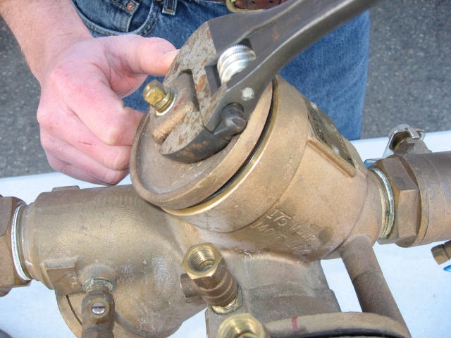
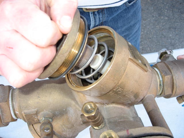
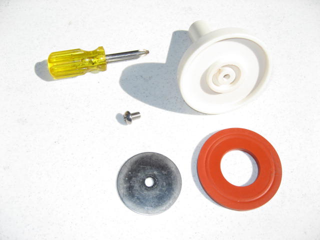
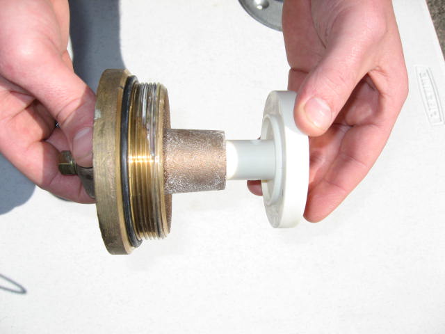
Let’s get started with the check valves. The check covers are threaded into the body and sealed with an o-ring. Using an adjustable wrench, loosen the cover by turning counter-clockwise. The check valve springs are not contained so there is a spring load on the covers. The spring and poppet are free once the cover has been removed. The check valve disc is accessible by removing the retaining screw and washer from the plastic poppet. The check valve seats are sealed by an o-ring and threaded into the body. There is no reason to remove the seat unless it needs to be replaced.
Mark:
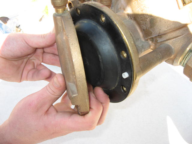
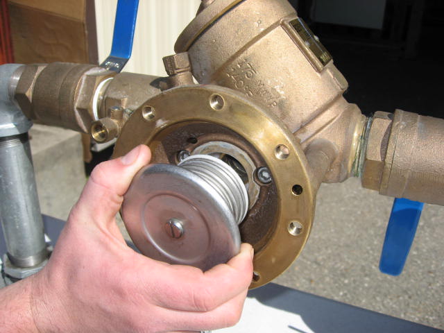
After servicing the check valves, we can turn our attention to the relief valve. The relief valve is located on the side of the assembly. The cover is sealed by the diaphragm and has a slight spring load. Once the cover bolts are removed, the diaphragm and cover are free. The relief valve assembly is o-ring sealed and can be pulled straight out of the body. On models produced before 1988 the relief valve seat was not replaceable. On models produced after 1988, the relief valve seat was threaded into the body and sealed by an o-ring.
Doug:
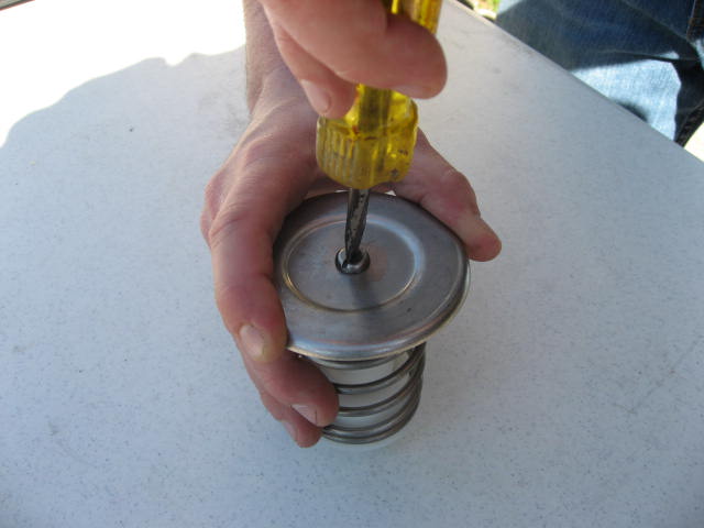
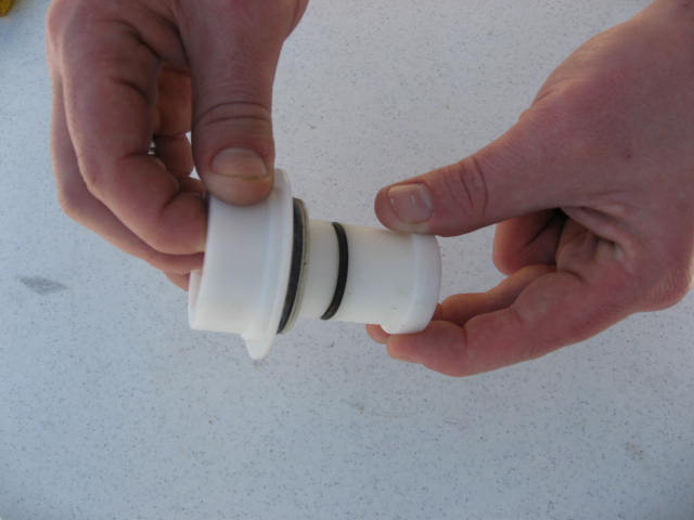
To replace the relief valve disc, simply remove the retaining screw and washer from the front of the stem. The relief valve assembly is spring loaded and must be disassembled to replace the stem o-ring. To do this, hold the stainless diaphragm plate firmly and remove the retaining screw. Once the retaining screw is removed, the spring, stem and bushing are free. The stem o-ring should be replaced and lubricant applied. Reassemble the relief valve assembly in reverse order.
Authors |
|
 Mark Inman |
In our line of work, we field questions from contractors and technicians concerning repairs, installations and general backflow prevention practices. We’d like to share some questions that we receive, as well as our answers. Everyone has different opinions on these subjects and we would like to hear yours.
Contact us with questions and ideas via email at: or mail us at: |
 Doug Taylor |
|


 24 Mar 2020
 Posted by BP Journal


