Question: I am working on a 1” Watts model 719. Could you guys give me an overview of the repair procedures so that I’ll know what to expect when I arrive? Also let me know if I’ll need any special tools for disassembly.
Mark:
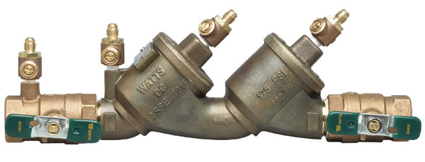
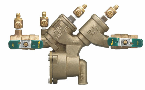
The Watts 719 is a double check valve assembly (DCA). This series is available in ½”-2” sizes and has been in production since 2003. The Watts 919 is a reduced pressure principle assembly (RPA) and has many of the same internal components as the 719 and the repair procedures for the check valves are identical. For the purpose of this article we will go over the repair for both units. Fortunately, no special tools are required to repair this series.
Doug:
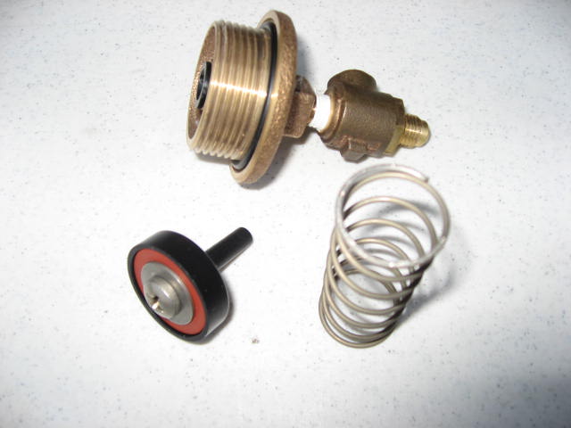
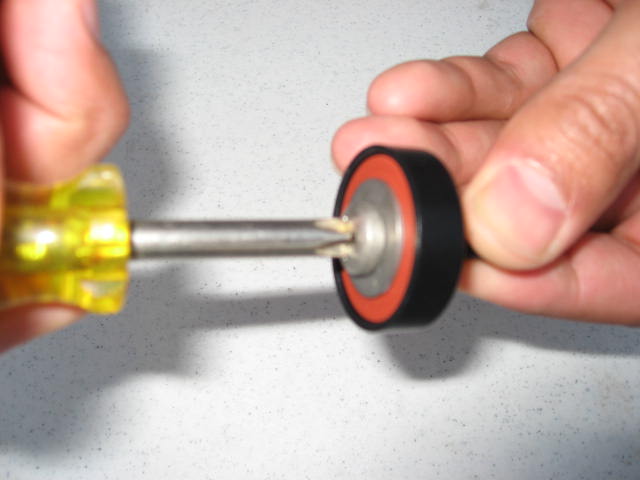
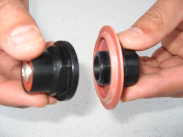
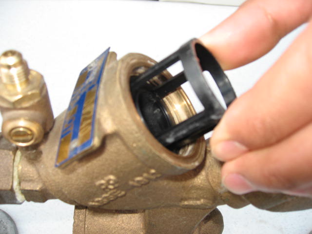
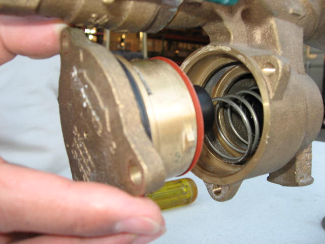
Let’s get started with the check valves for the 719 and 919. Using an adjustable wrench, loosen the check valve cover by turning counter-clockwise. The check valve springs are not contained. After removing the cover, the spring and check poppet are free. The check valve disc is accessible by removing the retaining screw and washer. To inspect or replace the check valve seat, simply grasp the reinforcement ring at the top of the seat and pull straight out. The check seats are sealed by an o-ring and simply pressed back into the body bore. Lubricate the o-rings and reassemble in reverse order.
Mark:
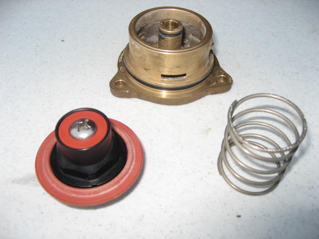
After servicing both checks, we can turn our attention to the relief valve of the 919. The relief valve is located on the bottom of the assembly. The relief valve cover is spring loaded and sealed by an o-ring. The RV cover has locking tabs that allow you to remove the cover bolts without having to apply constant pressure to the cover. After removing the (3) R.V. cover bolts, simply push in and turn counter-clockwise to remove. Note: The cover is under a slight spring tension.
Doug:
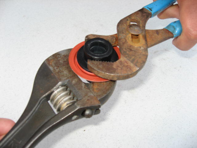
When removing the relief valve cover, the internal module should come out attached to the cover housing. The spring is loose and may fall out of the body. The relief valve seat is o-ring sealed. To remove, simply pull the seat straight out of the body. To replace the diaphragm, unscrew the RV stem assembly. Place a wrench on the flats of the disc holder, and place one on the flats of the plunger on the upper stem. When you reassemble the stem assembly, the molded step of the diaphragm should face toward the RV stem and disc. To access the RV disc, remove the retaining screw. Reassemble in reverse order. When replacing the cover, remember to line up the grooves on the cover with the grooves in the body and turn the cover clockwise ¼ turn so that it locks into position.
Authors |
|
 Mark Inman |
In our line of work, we field questions from contractors and technicians concerning repairs, installations and general backflow prevention practices. We’d like to share some questions that we receive, as well as our answers. Everyone has different opinions on these subjects and we would like to hear yours.
Contact us with questions and ideas via email at: imark@ American Backflow |
 Doug Taylor |
|


 04 Nov 2019
 Posted by BP Journal





1 Comment
Do you mind if I quote a couple of your posts as long as I provide credit and sources back to your blog? My blog site is in the exact same niche as yours and my visitors would genuinely benefit from a lot of the information you present here. Please let me know if this alright with you. Appreciate it!