I have a 1” ARI model RP-501. Can you guys give me an overview of this assembly and any tips that may help me service this assembly correctly?
Mark:
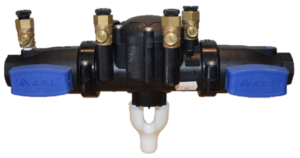
The ARI model RP-501 is a reduced pressure principle assembly and started production in 2016. This series is produced in ¾”- 2” sizes. The valve body is made of a black composite plastic material. What makes this assembly very unique is the fact that the inlet and outlet shut off valves are also made of a black nylon composite material. All the internal components can be removed through a single access cover. The check valves are modular in design and held in place with a retainer. No special tools are required to complete the repair of this assembly.
Doug:
The 1” assembly has a single access cover that is sealed by the relief valve diaphragm and is secured with eight Phillips head screws. There is a slight spring load on the cover, so be sure to keep pressure on it as you remove the screws.
Once the cover has been removed, the relief valve stem assembly and spring are free and can be inspected. To replace the RV diaphragm, remove the screw at the top of the RV stem. Once the screw is removed, the top plate is free and the diaphragm can be inspected or changed.
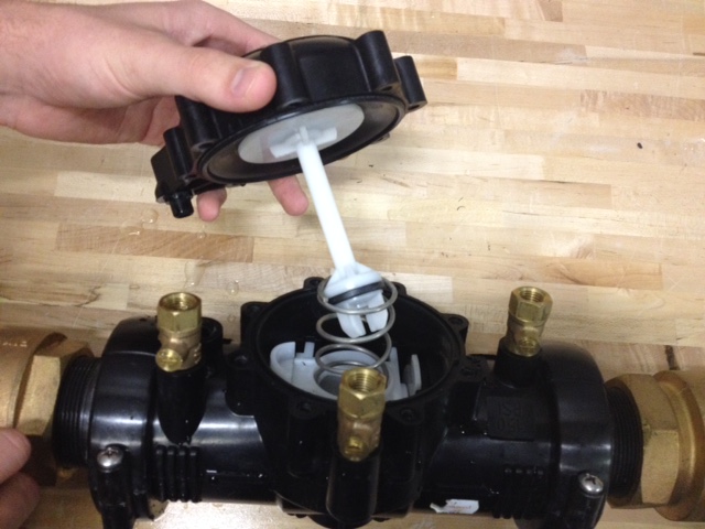
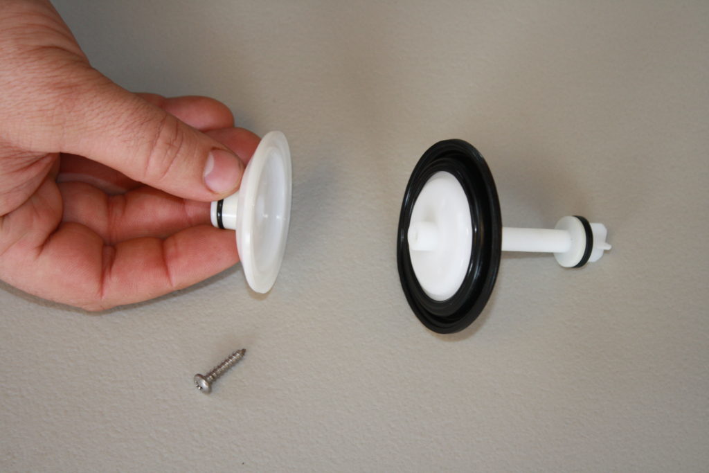
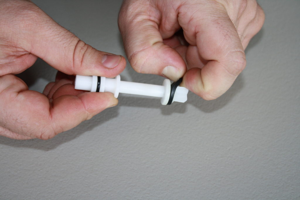
There is an o-ring located on the RV stem under the bottom diaphragm plate. Simply slide the bottom plate back to expose the o-ring. The relief valve disc is located at the bottom of the stem assembly and is held in place by the stem fin guide. The rubber disc must be pulled out from around the fin guide. Please note that the stem fin guide is not removable, so be careful not to damage it when removing the rubber disc. The relief valve seat is o-ring sealed and made of white plastic. The RV seat is located in the bottom of the device body and is pushed into the device body. The seat can be pushed out from the underside of the assembly.

Mark:
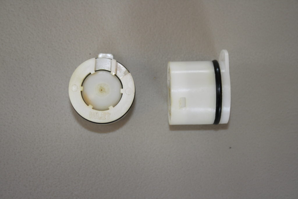
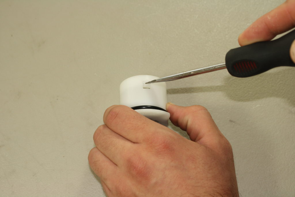
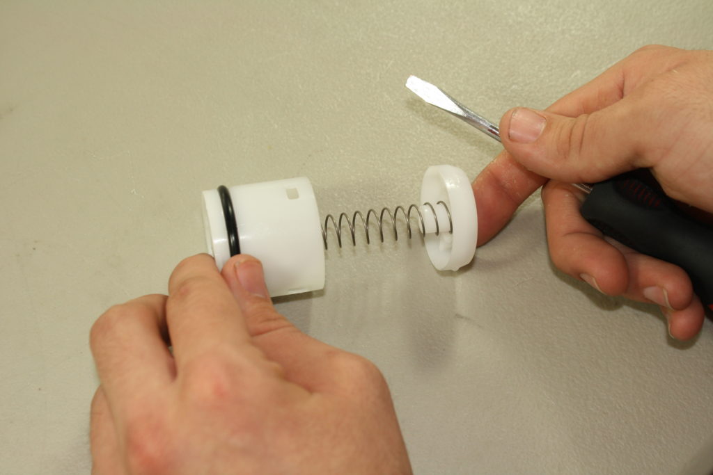
The check valve modules for the RP-501 are made of a white plastic and the springs are contained. The check valve modules are o-ring sealed into the body and held in place by a retainer. The check retainer is white plastic and will slide straight up and out of the device body. The check valves can be removed by first using a screwdriver to pry them from the body and then sliding them toward the access hole. To disassemble each check valve, locate the 3 tabs on the side of the check module. Use a small flat head screwdriver to press each tab toward the outlet of the module. Please note that the check modules are spring loaded, so hold securely during disassembly. The check poppet, spring and retainer are free once the spring tension is released. To remove the check disc, simply pry it from the poppet. Reassemble the check module in reverse order.
Doug:
At this point we can reinstall the checks by sliding them back into the body. The check retainer should slide into place very easily. If it does not, make sure the checks are fully seated into the body. The RV stem will insert through the hole in the retainer. The RV spring will rest on top of the check retainer. Before you reinstall the cover, be sure to examine your sensing line o-ring, which is located inside the sensing line passage of the body. Finally, remember that the diaphragm is what seals the access cover, so make sure that the ridge on the diaphragm lines up with the groove on the body before the cover screws are secured.
Authors |
|
 Mark Inman |
In our line of work, we field questions from contractors and technicians concerning repairs, installations and general backflow prevention practices. We’d like to share some questions that we receive, as well as our answers. Everyone has different opinions on these subjects and we would like to hear yours.
Contact us with questions and ideas via email at: or mail us at: |
 Doug Taylor |
|


 07 Feb 2019
 Posted by BP Journal





1 Comment
So glad to see these technical and easy to understand articles back in my in box!
Very much appreciated!